현재 위치
홈아두이노 모터 실드 R3 L298P

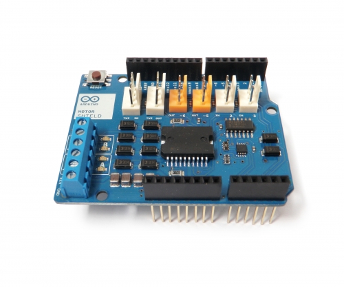
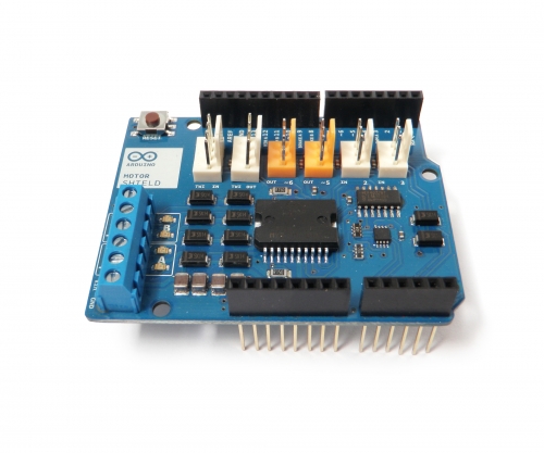
아두이노 보드에 적층하여 간편하게 사용 가능한 모터 구동 쉴드입니다.
The shield's pins, divided by channel are shown in the table below:
Function
pins per Ch. A
pins per Ch. B
Direction
D12
D13
PWM
D3
D11
Brake
D9
D8
Current Sensing
A0
A1
iIf you don't need the Brake and the Current Sensing and you also need more pins for your application you can disable this features by cutting the respective jumpers on the back side of the shield.
The additional sockets on the shield are described as follow:
Screw terminal to connect the motors and their power supply.
2 TinkerKit connectors for two Analog Inputs (in white), connected to A2 and A3.
2 TinkerKit connectors for two Aanlog Outputs (in orange in the middle), connected to PWM outputs on pins D5 and D6.
2 TinkerKit connectors for the TWI interface (in white with 4 pins), one for input and the other one for output.
Motors connections:
Brushed DC motor. You can drive two Brushed DC motors by connecting the two wires of each one in the (+) and (-) screw terminals for each channel A and B. In this way you can control its direction by setting HIGH or LOW the DIR Aand DIR B pins, you can control the speed by varying the PWM A and PWM B duty cycle values. The Brake A andBrake B pins, if set HIGH, will effectively brake the DC motors rather than let them slow down by cutting the power. You can measure the current going through the DC motor by reading the SNS0 and SNS1 pins. On each channel will be a voltage proportional to the measured current, which can be read as a normal analog input, through the function analogRead() on the analog input A0 and A1. For your convenience it is calibrated to be 3.3V when the channel is delivering its maximum possible current, that is 2A.
Package included:
1 x Motor Driver Module

아두이노 모터 쉴드 R3 사용 포트 | |
D0 | |
D1 | |
D2 | |
D3 | 모터 A PWM |
D4 | |
D5 | |
D6 | |
D7 | |
D8 | 모터 B Brake |
D9 | 모터 A Brake |
D10 | |
D11 | 모터 B PWM |
D12 | 모터 A Dir |
D13 | 모터 B Dir |
A0 | |
A1 | |
A2 | |
A3 | |
A4 | |
A5 | |
void setup() {
//Setup Channel A
pinMode(12, OUTPUT); //Initiates Motor Channel A pin
pinMode(9, OUTPUT); //Initiates Brake Channel A pin
}
void loop(){
//forward @ full speed
digitalWrite(12, HIGH); //Establishes forward direction of Channel A
digitalWrite(9, LOW); //Disengage the Brake for Channel A
analogWrite(3, 255); //Spins the motor on Channel A at full speed
delay(3000);
digitalWrite(9, HIGH); //Eengage the Brake for Channel A
delay(1000);
//backward @ half speed
digitalWrite(12, LOW); //Establishes backward direction of Channel A
digitalWrite(9, LOW); //Disengage the Brake for Channel A
analogWrite(3, 123); //Spins the motor on Channel A at half speed
delay(3000);
digitalWrite(9, HIGH); //Eengage the Brake for Channel A
delay(1000);
}
배송안내
- 배송비 : 기본배송료는 2,500원 입니다. (도서,산간,오지 일부지역은 배송비가 추가될 수 있습니다) 50,000원 이상 구매시 무료배송입니다.
- 본 상품의 평균 배송일은 0일입니다.(입금 확인 후) 설치 상품의 경우 다소 늦어질수 있습니다.[배송예정일은 주문시점(주문순서)에 따른 유동성이 발생하므로 평균 배송일과는 차이가 발생할 수 있습니다.]
- 본 상품의 배송 가능일은 0일 입니다. 배송 가능일이란 본 상품을 주문 하신 고객님들께 상품 배송이 가능한 기간을 의미합니다. (단, 연휴 및 공휴일은 기간 계산시 제외하며 현금 주문일 경우 입금일 기준 입니다.)
교환 및 반품안내
- 상품 택(tag)제거 또는 개봉으로 상품 가치 훼손 시에는 상품수령후 7일 이내라도 교환 및 반품이 불가능합니다.
- 저단가 상품, 일부 특가 상품은 고객 변심에 의한 교환, 반품은 고객께서 배송비를 부담하셔야 합니다(제품의 하자,배송오류는 제외)
- 일부 상품은 신모델 출시, 부품가격 변동 등 제조사 사정으로 가격이 변동될 수 있습니다.
- 신발의 경우, 실외에서 착화하였거나 사용흔적이 있는 경우에는 교환/반품 기간내라도 교환 및 반품이 불가능 합니다.
- 수제화 중 개별 주문제작상품(굽높이,발볼,사이즈 변경)의 경우에는 제작완료, 인수 후에는 교환/반품기간내라도 교환 및 반품이 불가능 합니다.
- 수입,명품 제품의 경우, 제품 및 본 상품의 박스 훼손, 분실 등으로 인한 상품 가치 훼손 시 교환 및 반품이 불가능 하오니, 양해 바랍니다.
- 일부 특가 상품의 경우, 인수 후에는 제품 하자나 오배송의 경우를 제외한 고객님의 단순변심에 의한 교환, 반품이 불가능할 수 있사오니, 각 상품의 상품상세정보를 꼭 참조하십시오.
환불안내
AS안내
- 소비자분쟁해결 기준(공정거래위원회 고시)에 따라 피해를 보상받을 수 있습니다.
- A/S는 판매자에게 문의하시기 바랍니다.
이미지 확대보기
아두이노 모터 실드 R3 L298P / L298P Dual Channel Motor Driver Module Motor Shield R3 For Arduino 5V ~ 12V Free Running Stop And Brake Function

비밀번호 인증
글 작성시 설정한 비밀번호를 입력해 주세요.
확인


